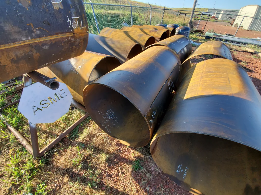
The ASME factor of a pressure vessel
In the ASME Boiler and Pressure Vessel Code (BPVC), the term “ASME factor” usually refers to the design safety factor or allowable stress factor. This factor defines the relationship between a material’s ultimate tensile strength (or yield strength) and the allowable stress value used in design calculations.
For most materials under ASME BPVC Section VIII, which governs pressure vessel design, the factor is typically set as:
Allowable Stress (S) = Yield Strength (or Tensile Strength) ÷ 3.5
This simplifies to a safety factor of 3.5. However, it’s important to remember that the actual factor depends on several variables, including material and operating conditions.
Material and Temperature:
The ASME factor changes based on the material and operating temperature. ASME BPVC Section II, Part D provides allowable stress values for different materials at specific temperatures.
Weld Joint Efficiency:
The type and quality of welds used in a pressure vessel significantly affect its allowable stress. Weld joint efficiency measures how well a weld transfers loads compared to the base material.
Welds examined with radiographic (X-ray) testing achieve higher efficiency because it identifies and repairs defects that could weaken the joint. On the other hand, welds that are partially examined or uninspected often have lower efficiency. This reduces the allowable stress for those parts of the vessel and may affect its structural integrity over time.
Division of Section VIII:
ASME BPVC Section VIII is divided into multiple divisions, each offering a different approach to design and safety:
- Division 1 focuses on design-by-rule principles. It uses predefined rules and formulas to ensure safety. This division applies a safety factor of 3.5 to account for uncertainties in material properties, construction, and operating conditions. This ensures a conservative approach to design.
- Division 2, also called “Alternative Rules,” emphasizes a detailed design-by-analysis method. It considers factors such as material behavior, stress concentrations, and fatigue in greater detail. With this in-depth analysis, Division 2 often allows lower safety factors compared to Division 1, enabling more efficient designs without compromising safety.
This distinction allows designers and engineers to choose the most suitable set of rules based on the project’s complexity, required safety margins, and the data available on material performance.
Key Considerations for ASME-Certified Pressure Vessels
Designing and constructing pressure vessels requires accounting for factors that impact performance, durability, and safety. The ASME Boiler and Pressure Vessel Code (BPVC) provides comprehensive guidelines to ensure vessels can handle various stresses, environmental factors, and loading conditions.
Below are the key considerations for engineers when designing pressure vessels compliant with ASME standards:
- Material selection and properties.
- Operating pressure and temperature.
- Fatigue and stress limits.
- Weld quality and efficiency.
Nature of Stress
The ASME BPVC distinguishes between primary stresses (caused directly by pressure) and secondary stresses (resulting from thermal expansion). Identifying the specific stresses a vessel will face is essential since their treatment and allowable values differ.
When designing a pressure vessel, engineers must refer to the relevant sections and tables in the ASME BPVC. These resources provide the allowable stress values for materials and the required safety factors based on the vessel’s operating environment. Primary stresses impact the structural integrity of the vessel, while secondary stresses may lead to deformation or fatigue. The ASME code offers methods to calculate both types, ensuring vessels remain safe under various conditions.
Fatigue Considerations
For vessels exposed to cyclic loading or unloading—such as pressure or thermal cycles—fatigue is a critical factor. Over time, repeated stress cycles weaken the material, which may lead to cracks or failure.
The ASME BPVC, particularly Section VIII, Division 2, outlines guidelines for evaluating fatigue in pressure vessels. Engineers analyze the number of stress cycles a vessel will endure and compare them to fatigue curves for the material. This process ensures the vessel operates safely over its lifetime, extending its service life and preventing unexpected failures.
Creep Considerations
Creep refers to the slow, time-dependent deformation of materials exposed to high temperatures for extended periods. In pressure vessels operating in such environments, creep can become a major design challenge.
The ASME BPVC offers guidelines for evaluating the effects of elevated temperatures on materials. By analyzing a material’s creep properties, engineers ensure the vessel retains its structural integrity throughout its operational life, even under extreme heat. This factor is especially critical in industries such as chemical processing and power generation, where equipment operates continuously at high temperatures.
Ligament Efficiency
In pressure vessels with multiple openings or closely spaced penetrations, the material between these openings (ligaments) plays a vital role in maintaining structural integrity. Calculating ligament efficiency ensures the vessel can withstand the pressures it encounters.
The ASME BPVC provides rules for determining ligament efficiency. These calculations help ensure that the material between openings supports the overall pressure load. Engineers use this data to adjust allowable stress levels, preserving the vessel’s strength even when it features multiple nozzles, manways, or other attachments.
Design Considerations for Pressure Vessels
Beyond stress-related concerns, engineers must consider other factors when designing pressure vessels. These include the shape and design of formed heads, external loadings, and transitional sections.
Formed Heads and Transitional Sections:
Pressure vessels often include formed heads, which may be elliptical, hemispherical, or torispherical. These heads are designed to withstand internal pressure while ensuring a smooth transition to the vessel’s cylindrical body.
The ASME BPVC provides formulas and guidelines to determine the appropriate thickness and design for these components. Properly designed formed heads distribute stress evenly, enabling the vessel to operate safely under all conditions.
External Loadings
While internal pressure is the primary load for most pressure vessels, external forces—such as wind, seismic activity, the weight of attached equipment, and piping-induced loads—also influence structural integrity.
The ASME BPVC offers detailed guidance for evaluating and addressing these external loads during design. This process includes assessing environmental forces and verifying that the vessel’s support and anchoring systems are sufficient. In regions with high winds or seismic activity, careful consideration of external loads ensures the vessel remains stable and safe over the long term.
Bolting and Flanged Connections
Pressure vessels often have flanged connections that are secured with bolts. The design, selection, and application of these bolts are crucial to maintaining the vessel’s integrity under high-pressure conditions. Ensuring that the correct bolts and gaskets are used is critical to preventing leaks and maintaining a secure connection between the flanges.
The ASME BPVC provides detailed guidelines for the proper selection of bolts and gaskets for use in flanged connections. These guidelines take into account the tensile strength, corrosion resistance, and temperature tolerance of the bolts. Additionally, the code outlines the torque specifications for tightening bolts to prevent over-tightening or under-tightening, both of which could compromise the vessel’s seal. Proper flanged connections ensure the vessel can maintain its pressure rating and operate safely over its lifespan.
Corrosion and Wear Allowances
Over time, pressure vessels are subject to corrosion and wear, especially when exposed to aggressive chemicals, high temperatures, or abrasive materials. This can reduce the wall thickness of the vessel, compromising its ability to contain pressure safely.
The ASME BPVC allows designers to add a corrosion allowance to account for the expected material loss over the vessel’s operational life. This means that during the design phase, additional material thickness is included to offset the effects of corrosion and wear. Regular inspections and non-destructive testing help to monitor the condition of the vessel and ensure that the remaining thickness stays within acceptable limits. By accounting for these allowances, engineers can extend the vessel’s lifespan and maintain safety throughout its use.
Quality Control and Quality Assurance
Ensuring the quality of the materials and fabrication processes is paramount for the safety and performance of pressure vessels. The ASME BPVC mandates strict quality control (QC) and quality assurance (QA) procedures to verify that vessels are constructed according to industry standards.
These procedures include material traceability, which ensures that every material used in the vessel can be traced back to its source, providing confidence in its quality and consistency. Additionally, welding procedures must be carefully controlled, and all welders must meet ASME’s stringent qualification requirements. To ensure that the vessel is free from defects, non-destructive testing (NDT) methods, such as ultrasonic and radiographic inspections, are used to check for internal and surface flaws. Finally, hydrostatic testing is performed to validate that the vessel can handle its design pressure without leaks or deformation, ensuring its safety before it enters service.
Documentation and Certification
For a pressure vessel to carry the ASME “U” stamp, comprehensive documentation must be maintained throughout the design, fabrication, and testing processes. This documentation is essential for demonstrating that the vessel complies with ASME standards and ensuring future traceability and inspections.
The required documentation includes material test reports, which verify the quality and properties of the materials used in the vessel. Welder qualifications and welding procedure specifications (WPS) must also be documented to ensure that the fabrication was performed by qualified personnel using approved techniques. Additionally, reports from non-destructive testing (NDT) and hydrostatic testing must be included to confirm that the vessel has passed all necessary inspections. This documentation not only proves the vessel’s compliance but also serves as a reference for future maintenance and inspections, ensuring the vessel’s long-term safety and reliability.
Comprehensive Approach to Pressure Vessel Safety
In summary, the design and fabrication of pressure vessels according to the ASME BPVC is a multifaceted process that involves careful consideration of various factors, including material selection, corrosion allowances, bolting connections, and detailed quality control measures. By adhering to these rigorous standards, engineers can ensure that pressure vessels function safely and efficiently in a wide range of industrial applications.
When followed diligently, the ASME guidelines provide peace of mind to industries relying on pressure vessels, as they significantly reduce the risk of catastrophic failures and enhance the overall safety and performance of critical equipment. This comprehensive approach ensures that vessels meet the highest levels of safety, reliability, and compliance, making them integral components in the oil and gas, chemical, power generation, and many other industries.
Need a reliable partner?
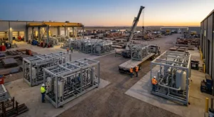
Red River specializes in the design and manufacturing of pressure vessels. We also fabricate related items such as prefabricated spools and skid packages.
Reach Out to us today and experience the Red River difference. Where American Made and American Values come together, we care more.
FAQ: Understanding ASME Factors and Pressure Vessels
What is the ASME factor in pressure vessel design?
The ASME factor, often referred to as the “safety factor,” in pressure vessel design is a critical element defined by the American Society of Mechanical Engineers (ASME). It’s a multiplier applied to the maximum allowable stress in a pressure vessel’s material, ensuring the vessel can withstand pressures beyond its normal operating conditions. This factor is crucial for ensuring safety and reliability, especially under varying operational stresses and temperatures.
How does the ASME factor influence the selection of materials for pressure vessels?
Material selection for pressure vessels is significantly influenced by the ASME factor. Materials must not only be suitable for the vessel’s intended use but also capable of safely handling stress levels determined by the ASME factor. This means choosing materials with appropriate strength, corrosion resistance, and durability to exceed the minimum requirements set by ASME standards, thus ensuring long-term safety and functionality.
Can the ASME factor vary based on the type of pressure vessel?
Yes, the ASME factor can vary depending on the type and use of the pressure vessel. Different types of vessels, such as those used for gas storage versus liquid storage, may encounter different operational stresses and temperatures. ASME codes take these variations into account, setting different safety factors for different vessel types and applications to ensure optimal safety and performance.
What role does the ASME factor play in pressure vessel testing and certification?
During pressure vessel testing and certification, the ASME factor plays a pivotal role. Vessels are tested under conditions that simulate the stresses they would face in real-world operations, often exceeding normal operating pressures. The ASME factor ensures that these vessels can withstand these tests without failure, which is crucial for certification under ASME standards. This process guarantees that the vessels meet the highest safety and quality benchmarks before they are put into service.
How do changes in ASME codes affect existing pressure vessels?
Changes in ASME codes can have significant implications for existing pressure vessels. If a code revision introduces stricter safety factors or material requirements, existing vessels may need to undergo reassessment or modification to comply with the new standards. This ensures that all pressure vessels, regardless of their manufacturing date, adhere to the latest safety and quality guidelines, thereby maintaining operational safety and integrity.
Related Blog Post
Where Should Industrial Tanks Be Located?
How Do Tie-Ins Impact Downtime
What Are Thermal Storage Tank Design Parameters?
Can Modularization Speed Builds on Industrial Projects?
Which Weld Procedures Are Common in Vessel Fabrication
- Understanding Pressure Vessel Sizing for Optimal Performance
- Understanding Pressure Vessel Sizing for Optimal Performance
- Understanding the Lifespan of Pressure Vessels: Key Factors & Maintenance
- What ASME Defines as a Pressure Vessel | ASME BPVC Section VIII Guide
- Essential Criteria for Designing a Pressure Vessel
- Preferred Failure Theory in Pressure Vessel Design Explained
About Author